
Product
Aluminum Mainboard Bracket
Material
Aluminum 6063-T6
Process
Precision CNC Milling
Industry
Military / Defense Electronics
Thickness Tolerance
5.1 mm 0 / −0.05 mm
Flatness
≤ 0.1 mm full surface
Thin-wall aluminum CNC milling for military and defense electronics applications demands a level of process discipline that goes far beyond standard commercial machining. When a component serves as the primary structural support for a motherboard assembly inside a ruggedised portable military computer, dimensional instability, surface chatter, or flatness deviation are not acceptable outcomes — they are mission-critical failures.
This case study documents Precimach’s approach to the precision CNC milling of an Aluminum 6063-T6 mainboard bracket for a military portable computer system — covering the engineering challenges of thin-wall aluminum machining, the five-step process developed to achieve the required tolerance and surface finish, and the custom fixturing solution that was central to the result.
Precimach specialises in precision CNC milling for aerospace, military, and high-performance electronics components. View our CNC milling capabilities →
Project Overview: Thin-Wall Aluminum CNC Milling for Defense Electronics
The aluminum mainboard bracket is a precision structural component designed for integration into rugged military-grade portable computer systems. It provides the primary mechanical mounting platform for the motherboard assembly and associated circuit boards — maintaining dimensional consistency under vibration, thermal cycling, and the physical stresses of field deployment.
The component is manufactured from Aluminum 6063-T6 — a medium-strength, high-corrosion-resistance alloy widely specified for structural electronics enclosures due to its excellent surface finish response and dimensional stability after heat treatment. The T6 temper provides a controlled balance of hardness and machinability suitable for precision thin-wall milling, provided the process is managed correctly.
The drawing specified a wall thickness of 5.1 mm with a unilateral negative tolerance of 0 / −0.05 mm — the finished part could be no thicker than nominal and no more than 0.05 mm undersize. Combined with a flatness requirement of ≤ 0.1 mm across the full surface and zero chatter marks, this represented a demanding combination for a thin-wall component with a high area-to-thickness ratio.
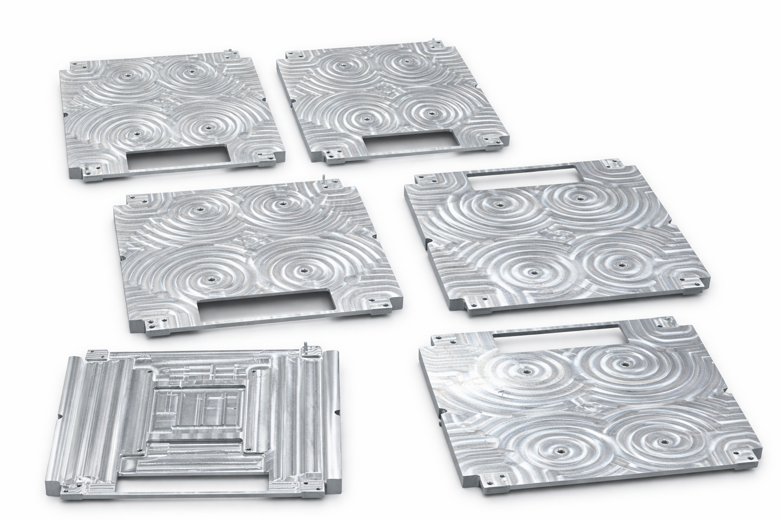
raw material and pre-machining condition
| Parameter | Specification |
|---|---|
| Material | Aluminum 6063-T6 |
| Manufacturing Process | Precision CNC Milling |
| Thickness Tolerance | 5.1 mm, 0 / −0.05 mm (unilateral negative) |
| Flatness Requirement | ≤ 0.1 mm across full surface |
| Surface Finish | No chatter marks; uniform machining texture |
| Application | Structural support for military portable computer motherboard assembly |
Engineering Challenges: Why Thin-Wall Aluminum CNC Milling Is Difficult
Thin-wall aluminum CNC milling combines several competing process difficulties that do not appear in standard solid-section machining. Aluminum 6063-T6 contains residual internal stresses from extrusion and T6 aging. When material is removed during machining, these stresses redistribute and can cause the workpiece to warp — making it impossible to hold flatness and thickness tolerance simultaneously without deliberate process engineering.
① Post-Roughing Deformation
Rough milling rapidly redistributes internal stresses. Without a controlled rest period, the part will bow or twist before finishing — making the final tolerance impossible to achieve regardless of finish pass precision.
② Unilateral Negative Tolerance
A tolerance of 0 / −0.05 mm is asymmetric — the part cannot be oversize at all, and can only be undersize within 0.05 mm. This eliminates the ability to use the safe side of a bilateral tolerance and requires exceptional dimensional control.
③ Surface Chatter from Insufficient Support
Thin-wall sections flex under cutting force. If the workpiece is not fully supported across its back face during finishing, the cutter produces chatter marks that violate the surface finish requirement. Standard vise clamping cannot provide the full-face support needed.
④ Clamping-Induced Flatness Error
If the fixture clamps the part while it is slightly bowed, the part appears flat during machining but springs back to a non-flat state when unclamped — a hidden error that only appears at final inspection.
Root cause summary: The combination of unilateral negative thickness tolerance, zero-chatter surface finish, and ≤ 0.1 mm flatness on a large-area thin-wall component required a purpose-engineered process sequence and custom fixturing solution. Standard machining practice would not have achieved this result.
Optimised 5-Step CNC Milling Process
Precimach’s process engineering team developed a five-step sequence to address each failure mode systematically — eliminating stress-induced deformation before it could affect final dimensions, and ensuring full workpiece support during the finish pass.
Stress Relief Annealing — Before Any Machining
Before the first cut, all raw Aluminum 6063-T6 blanks underwent controlled stress relief annealing. This thermal process reduces the magnitude of internal residual stresses introduced during extrusion and T6 processing. By reducing the initial stress state of the blank, the magnitude of deformation during subsequent material removal is significantly reduced. This step is not optional for tight-tolerance thin-wall work — it is the foundation of the entire process.
Controlled Rough Milling — Balanced Material Removal
A balanced, symmetrical material removal strategy removed stock from both faces progressively rather than completing one side entirely before starting the other. This minimises asymmetric stress redistribution that causes bowing. Cutting parameters were optimised to reduce heat generation and cutting force. A uniform finishing allowance was left on all surfaces for the precision pass.
24-Hour Natural Aging — Stress Stabilisation
After rough machining, all parts were set aside for a minimum of 24 hours of natural aging at ambient temperature. Remaining internal stresses equilibrate during this period. Any residual tendency for the part to warp expresses itself during this rest period — before the finish pass locks in the final dimensions. Parts showing out-of-tolerance deformation were identified and corrected before proceeding to finishing, rather than discovering the problem at final inspection.
▶ CNC milling process — from rough stock to finished military bracket:
This video shows the actual CNC milling process and finished component — from precision finish milling using the custom contoured fixture through to the completed military mainboard bracket ready for inspection.
Pay attention to the surface texture achieved on the finished bracket: uniform machining marks with zero chatter — the direct result of full-face fixture support, correct spindle speed, and controlled feed rate working together.
Full thin-wall aluminum CNC milling sequence — stress relief, rough milling, aging, custom fixture verification, precision finish pass
Precision Finishing with Custom Contoured Fixture
The most critical process element was the design and fabrication of a custom contoured fixture with reverse adjustment screws. Standard vise clamping provides support only at the edges — leaving the central area free to vibrate during finishing. The custom fixture was profiled to match the exact back-face geometry of the bracket, providing full-area contact support across the entire workpiece back surface. The reverse adjustment screws allowed the contact profile to be fine-tuned to the actual part shape — compensating for any minor residual bow remaining after the 24-hour aging period. With the part fully supported, high spindle speed and controlled feed rate eliminated chatter completely, producing the uniform machining texture required by the drawing.
Feeler Gauge Verification — Before the Finish Pass
Before committing to the final finishing cut, feeler gauges were used systematically to verify full surface contact between the part and the custom fixture across all critical areas. A feeler gauge that can be inserted between part and fixture indicates a gap — meaning the part is not fully supported and chatter will occur. Only parts with confirmed full-face contact proceeded to finishing. This verification step is what enables consistent, batch-level confidence in the 0 / −0.05 mm thickness tolerance — replacing reliance on operator feel with a measurable confirmation standard.
Process note: The custom contoured fixture and feeler gauge verification protocol developed for this project are now part of Precimach’s standard tooling library for thin-wall precision milling — improving capability and consistency for all subsequent thin-wall milling orders.
Quality Inspection & Verification Results
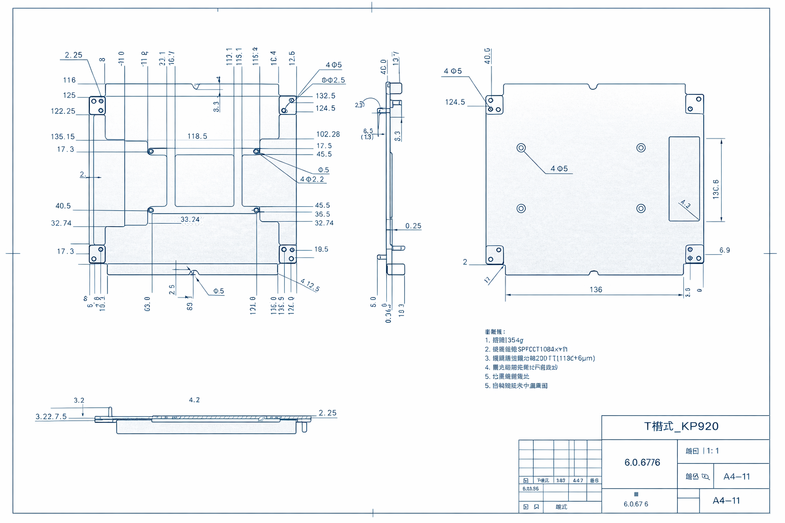
post-machining inspection, thickness and flatness verified
Final inspection was conducted using precision measurement instruments including calibrated micrometers and surface plate flatness verification. Surface integrity was visually and tactilely assessed for the presence of chatter marks or vibration-induced patterns. All dimensions were recorded and compared against drawing tolerances before parts were released.
✓
Thickness within specification
5.1 mm, 0 / −0.05 mm — confirmed across all measurement points on every part
✓
Flatness ≤ 0.1 mm
Full-surface flatness verified — no spring-back deformation after unclamping
✓
Zero chatter marks
Uniform machining texture across the full surface — no vibration patterns or tool-induced defects
✓
Fully compliant with military engineering requirements
All dimensional and surface finish requirements met — zero rework or re-inspection
Technical Note: Fixture Engineering for Thin-Wall Precision Milling
For engineers and procurement professionals sourcing thin-wall precision CNC milled components for aerospace, defense, or electronics applications, the fixture engineering approach in this case study addresses a fundamental challenge: how to hold a large, thin, potentially slightly bowed workpiece in a way that provides full cutting support without introducing clamping-induced distortion that will appear after part release.
The three most common failure modes in thin-wall aluminum CNC milling — post-roughing deformation, chatter from insufficient support, and clamping-induced flatness error — are all addressed through process sequence and fixture design rather than simply tightening machining parameters. A supplier who understands this will design the process around the geometry; a supplier who does not will attempt to compensate with slower feeds, with inconsistent results.
When evaluating CNC machining suppliers for thin-wall aluminum components in military or aerospace applications, the ability to describe their stress relief protocol, aging strategy, and fixture engineering approach — not just their machine specifications — is the most reliable indicator of process maturity for this class of work.
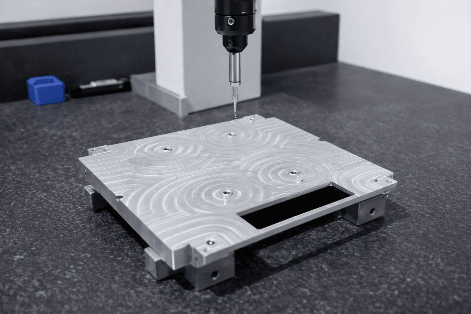
uniform texture, zero chatter marks, clean edge definition
For further technical reference on GD&T flatness and form tolerancing standards applied to precision machined components in aerospace and defense applications, the ASME Y14.5 Dimensioning and Tolerancing standard is the internationally recognised framework used by US military, aerospace, and defense electronics manufacturers for specifying flatness, profile, and form tolerances on precision machined parts.
Industry reference: ASME Y14.5 — Dimensioning and Tolerancing provides the GD&T framework for specifying flatness, profile, and form controls on precision machined components — the standard used by US military and aerospace OEMs to define and verify dimensional requirements on structural electronics hardware.
Have a Thin-Wall Precision Milling Challenge?
If you are sourcing precision CNC milled aluminum components for military, aerospace, or high-performance electronics applications — and your current suppliers are struggling with flatness, chatter, or tolerance consistency on thin-wall parts — Precimach has the process engineering capability to deliver where standard shops fall short.
Ready to discuss your precision CNC milling project?
Precimach is an ISO 9001 certified CNC machining factory in Suzhou, China — specialising in precision CNC milling for aerospace, military, and electronics components. We combine advanced 5-axis milling capability with custom fixture engineering and rigorous process sequencing to deliver tight-tolerance thin-wall components that standard shops cannot consistently achieve.
- Thin-wall aluminum milling — stress relief, aging, and custom fixturing included
- Tight tolerance capability to ±0.01 mm and tighter on critical features
- Materials: aluminum alloys, titanium, stainless steel, engineering plastics
- Military, aerospace, and electronics industry experience
- ISO 9001 certified — full dimensional inspection reports provided
- DDP shipping to USA — 3–5 days airfreight after production